CF adapter for Toshiba portables


Intro
This project started off with my Toshiba collection, Many of these early Toshiba T-Series have an expansion slot in the back. Looking through the maintenance manual's for these Toshiba's I found out that they just used the ISA bus with a different connector and formfactor for the expansion slot.
I already had some of Lo-tech's XT-CF cards and wanted something similar for the Toshiba slot. Therefore this card is based entirely on Lo-tech's design, I used the schematics on his website with some small changes, Of course I asked James if he was cool with that.
Where to buy?
For now these are available from my eBay store both fully assembled as well as in a Kit form.
Update sep 2022: all sales of the CF adapter have stopped, you can now order the 3in1 board with the "CF only" option for the exact same functionality. 3inONEder for Toshiba portables#Where to buy?
Features
The card has an easily accessible CF card slot. which allows you to expand upgrade or replace the storage of your Toshiba portable up to 8.2GB.
The XT-ide BIOS on the card allows booting from the CF card.
On Toshiba portables with an internal IDE controller the BIOS on this card can also be configured to control the internal IDE controller. This allows you to both use the CF card slot and/or replace the internal drive with any standard IDE drive.
Compatible Toshiba models
This card is compatible with every Toshiba model that has the expansion slot, or as it is named in the official Toshiba documentation "Toshiba proprietary expansion slot - "A" form factor".
- T1100 PLUS (not T1100)
- T1200
- T1600
- T2100 from 1986 (not the later "satellite T2100")
- T3100 (E)(sx)
- T3200sx(c) (not T3200)
- T5100
- T5200(c)
Some of the Japanese models J-3100… have the same expansion slot and should work as well, not sure. I have not been able to test this yet however.
Installation instructions.

- Make sure the computer is turned off.
- Locate the expansion port on the back of your Toshiba portable. (T1600 has this on the left side)
- Remove the two screws securing the expansion port cover and remove the cover plate.
- Insert the CF card adapter board and 3D printed bracket. (it might be easier to align and install the card first and then the bracket)
- Resecure the two screws again. (do not overtighten them in the 3D printed bracket)
- Install a Compact Flash card via the cutout in the bracket. (up to 8GB)

Programming the XTide bios.
Important: If you order the card from me, and tell me what Toshiba model the card will be used in I'll pre-program the card for you.
All the files discussed in this document can be downloaded here.
(extract these files somewhere you can access from the portable from which you want to program the ROM with. Floppy, Hard Disk or CF card)
Configuration files
- FLASH.EXE “Lo-tech XT-CF flash utility” For flashing config to ROM
- XTIDECFG.COM XT-IDE configuration editor
- XT.BIN Pre-configured for XT class machines (8088 & 8086)
- AT.BIN Pre-configured for 286 and higher machines
- AT-INT.BIN Same as “AT”, with support for internal IDE controller
Which pre-configured BIOS to use for which Toshiba portable?
- Use “XT.BIN”for XT class machines.
- T1100 PLUS
- T1200
- T2100
- Use “AT.BIN” for 286 and higher machines.
- T1600
- T3100(e)(sx)
- T3200sx(c)
- T5100
- T5200(c)
- The “AT-INT.BIN” file is only for portables that also already have an IDE controller on board, only use this if you want to change out the internal HDD for another IDE drive or adapter. The original Toshiba BIOS has a lot of restrictions when it comes to HDD’s, it often only supports a few specific Conner disks. With this configuration the BIOS on our board will also control the internal IDE controller therefore bypassing the restrictions of the original Toshiba BIOS.
- T1600 (not /40 model, it doesn't have an IDE controller)
- T3100e
- T3200sx(c)
- T5100
- T5200(c)
Flashing a configuration to ROM.
- Make sure the config (.BIN) file is in the same directory as the Flash utility.
- Run the following command:
FLASH “CFG.BIN” “base-address”- With “CFG.BIN” being the configuration you want to flash.
- With “base-address” being the base address for the ROM, “C800” on my board.
- EXAMPLE:
FLASH XT.BIN C800
- After Flashing is done, reboot.
Editing a Configuration.
This is only for if you want to change something about the pre-configured files I've made, for example: change the default boot order.
- Run “XTIDECFG.COM” to open the configuration editor.
- Open the configuration you want to edit with the “Load BIOS from file” option.
- Change the configuration as you like.
- use "Save BIOS back to original file"
- Exit the configuration editor.
- Now you can flash the configuration.
IMPORTANT: after editing a configuration always use the “Save BIOS back to original file” option, do not try to flash from within the Configuration program. Use the stand alone Flash utility as described above.
Technical data
Schematic and board layout


Component list
| Part | Qty | Value | Component |
|---|---|---|---|
| C1-5 | 5 | 0.1µF | 0603 ceramic capacitor |
| C6 | 1 | 10µF 16V | electrolytic capacitor |
| CF1 | 1 | 3M N7E50-Q516RB-50 | |
| IC1-2 | 2 | SOIC-20W 74HCT688D | |
| IC3 | 1 | SOIC-16 74HCT139D | |
| IC4 | 1 | DIP-32 SST 39SF0x0A or AMIC A29010-70F | |
| R1-3 | 3 | 10K | 0603 resistor |
| J1 | 1 | KEL 8801-060-170L or 3M P50-060S-RR1-EA | |
| JP1 | 1 | “ROM ENABLE” solder shut or place optional 2.54mm jumper or switch |
(optional, it is possible to install an activity LED and current limiting resistor at parts: "LED" and "R5")
3D printed bracket
Want to print your own bracket in a different material or colour? STL files are available here.
Soldering tips.
Important: This is not a detailed instruction of how to solder, I don't recommend soldering this yourself if you haven't done SMD parts before, take a good look at the CF card slot, this is very hard to solder. I'd recommend using a good temperature controlled soldering iron, leaded solder, plenty of flux and maybe a hot air rework station for if you screw up. ;)
I personally like to start with the CF card slot as it is the most difficult to solder.
Make sure you solder the CF card slot on the right place, there are 2 possible places depending on the configuration.
- Normal configuration (EXTERNAL) compatible with all Toshiba models, This is how I configure the cards that I sell unless specifically asked differently, requires a 3D-printed bracket for easy access. Place the card slot closest to the edge. (see picture below)
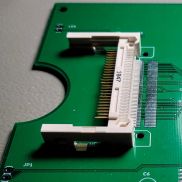
External

- Internal configuration, only compatible with T1100+,T1200,T1600 and T3100sx. This one doesn't need the 3D-printed bracket, you can just replace the stock Toshiba blank plate to close the expansion slot. For this configuration you will need to install the card slot on the pad furthest from the edge. (see picture below)
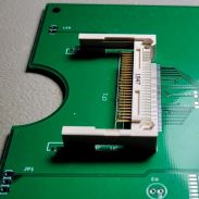
Internal

Then JP1, this is to enable the ROM and should be enabled for normal use. You could install an optional jumper or switch here but I just solder them shut as this does not need to be changed under normal use. (see picture below).

The rest of the components are up to you, everything is labeled and should be pretty easy to put together. ( also see the component list above)
After all components have been soldered and inspected, you are not quite done yet. Unless you specifically asked me to program the ROM for your device at the time of purchase, you will need to program the ROM yourself. Luckily this isn’t too hard to do. Just one DOS command and you are ready to go. Programing instructions
Useful external links
- The board is based on Lo-tech’s “XT-CF-lite” design with a fixed IO port address (300h - 31Fh) and ROM address (32KB at C800h). So much of the info on his website will also apply to my board. https://www.lo-tech.co.uk/wiki/XT-CF-lite_rev.2
- Lo-tech XT-CF flash utility: https://www.lo-tech.co.uk/wiki/Lo-tech_XT-CF_flash_utility
- XT-IDEuniversalbios - Manual: https://code.google.com/archive/p/xtideuniversalbios/wikis/Manual_v2_0_0.wiki