Connecting an IBM 5175 PGC display to a VGA output

This is a quick summary of a project I did a couple of years ago because I've been getting questions about how to do this.
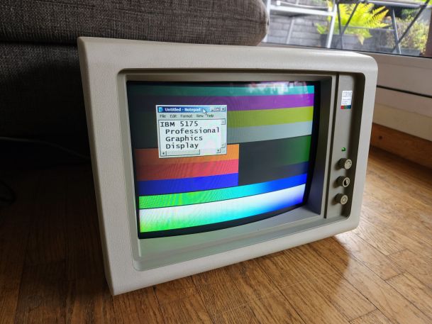
I picked up two IBM 5175 displays in a lot with IBM PC and XT stuff. Unfortunately I didn't get an IBM PGC card to go with it. So how do I test / use them?
When we look look at the resolution of the monitor we can see that it runs at 640x480 at 60Hz. now this should sound familiar as it's basically the same as a standard VGA signal.
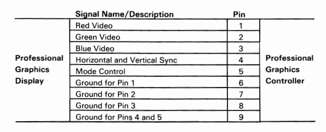
So lets take a look at the signals:

| Pin 1 | RED |
|---|---|
| Pin 2 | GREEN |
| Pin 3 | BLUE |
| Pin 5 | GND |
| Pin 6 | RED_GND |
| Pin 7 | GREEN_GND |
| Pin 8 | BLUE_GND |
| Pin 10 | GND |
| Pin 13 | HSync |
| Pin 14 | VSync |
I left out all the VGA ID pins as they are not required and we will not use them.
From comparing the PGC and VGA signals we can see that they both use separate RGB signals, they also both have a separate ground per colour.
That leaves us with the sync signals and the mode control on the 5175. the mode control switches between PGC mode and CGA emulation mode, we won't need to switch and therefore can leave this pin disconnected. (I haven't had an issue with leaving this floating)
So that leaves us with only the sync signals. The VGA standard uses separate horizontal and vertical sync signals while the 5175 uses a combined horizontal and vertical sync, similar to a composite sync signal.
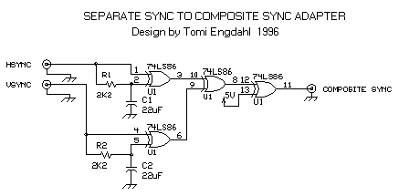
Now to adapt this I could try and design a simple circuit myself, but why do that when this is being done all the time by people for years. So a quick search online comes up with this circuit. This should do exactly what we want: combine the separate sync signals into a composite sync signal.

As you can see this is a very simple circuit with only 5 components, 2 resistors, 2 capacitors and 1 IC
| component | value | type |
|---|---|---|
| R1, R2 | 2200 Ohm | resistor |
| C1,C2 | 22 µF | capacitor |
| U1 | 74ls86
or 74HCT86 |
We will also need a female DE-9 connector to connect the display to and a male DE-15 connector to connect to our VGA card. As well as a way to provide +5V to the IC, a power socket or usb socket for example.
I had a DE-9 breakout board laying around but didn't have a DE-15 connector laying around so I use an old VGA cable for testing.
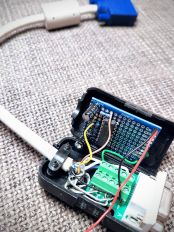
Here is the little prototype I made, I placed the components so that it would all fit in the plastic case of the breakout connector. I also used an old USB cable for power.

